
Estimate Shipping

| Carrier | Estimated Delivery | Price |
|---|


A unique strobe sequencer systems featuring 8 Xenon lamps per board, creates mesmerizing eye-catching effect for advertisement, shows, signaling and security.
12v-powered, Expandable up to 128 boards, 7 animation patterns, adjustable flash rate.
A special and unique strobe system that features 8 flash lamps on each board.
Create long strips by daisy-chaining the boards, giving a mesmerizing eye-catching effect.
Chain Flash System INTRODUCTION
This extendable flash sequencer allows you to create eye-catching signage, stage lighting effects, store fronts, emergency warning lighting and more.
Having 7 pre-programmed sequence patterns, wou will probably find your preference, which will be saved as the default pattern on powering the module. the system can consist of just a single controller board, and up to 128 extentions boards that will be all powered by the first controller board in the chain.
Applications:
SETUP PROCEDURE
On first power-on, the user needs to configure the controller board to define the total number of boards in the chain (including the controller board). It is essential for correct operation.
1. Hold the MODE button pressed, then connect the controller board to 12v power source
2. After about a second, the 8th flash lamp will fire once, indicating it is set to 1 board in the chain.
3. Release the MODE button immediately after the first flash
4. Press the MODE button (short click) once for increasing the board number to 2 (if needed)
5. The 8th flash lamp will fire twice, indicating it is set to 2 boards in the chain.
6. Repeat steps 5-6 as needed to reach your total board count on the chain.
7. 5 seconds later, the 8th lamp will fire the equivalent number of times as boards count in the chain.
8. Setup is finished, and the first pattern will start animating right away.
For example - If you have 1 controller board and 2 extension boards (total 3), configuration is as following:
Press MODE > Apply 12v > 1 flash > Press MODE > 2 flash > Press MODE > 3 flash > 5 seconds > 3 flash > End
SEQUENCE PATTERNS
On board power-up, the pattern saved in the controller memory will start animating immediately.
For selecting a different animation pattern, just press the MODE button once.
The new pattern will be saved to the controller’s memory, and start animating immediately.
FLASH RATE (SPEED)
The chain’s animation speed (flash rate) is set by the onboard trimmer marked “RATE” on th back of the controller board. Flash rate is adjustable between roughly 1Hz to 25Hz, That is 1 flash per second to 25 flashes per second.
TRIGGER / ENABLE INPUT (EXTERNAL CONTROL)
The “TRIGGER” input allows you to externally control the flash timing fo the existing sequence patterns.
More precisely, it acts as a “PAUSE” (active low) control, that will stop the chain animation at its current location, until the input goes high again. Then the controller resume playing the animation from the paused location.
The animation speed is still dependent on the onboard “RATE” trimmer, so it is recommended to set it to the maximum flash rate, if you desire a precise control using the external trigger method.
The signal has to go back low immediately if you wish to fire the next flash only, so the controller is paused again.
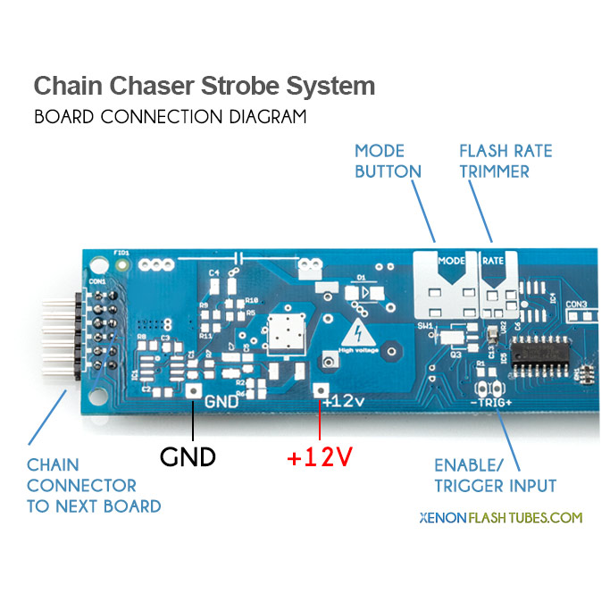
On the board, the “TRIG +” pad corresponds to the ENABLE input, internally pulled high for normal operation when no external control is needed. The “-” pad is GND, which allows using a simple NPN transistor for control.
WARNING: This kit involves High Voltage up to 800v which is stored in big capacitors even long after turning the unit off. THIS VOLTAGE CAN CAUSE SEVERE DAMAGE AND INJURY. Never touch any of the components and always discharge the capacitor before working on it. Always keep in a well insulated project enclosure.
BY FOLLOWING THESE INSTRUCTIONS YOU AGREE TO BE THE ONLY RESPONSIBLE FOR ANY DAMAGE THAT MIGHT BE CAUSED BY DOING SO. WORK CAREFULLY AND FOLLOW WARNINGS
According to the following scheme, connect the power wiring following the right polarity.
A unique strobe sequencer systems featuring 8 Xenon lamps per board, creates mesmerizing eye-catching effect for advertisement, shows, signaling and security.
12v-powered, Expandable up to 128 boards, 7 animation patterns, adjustable flash rate.