
Estimate Shipping

| Carrier | Estimated Delivery | Price |
|---|


A DIY assembly kit for Optically-triggered ("slave") Photography Flash unit, powered by 5v-6v (4xAA batteries)
Soldering skills needed, comes as a DIY kit, with clear and easy instructions (found below)
This kit is an Optical-triggered Powerful "Slave" photography flash.
it powers using a 5v-6v source like a wall adapter or 4xAA batteries,
And will automatically fire itself (by optical detection) when another flash is fired nearby.
Module Specifications
• Working voltage: 5v (4v-6v)
• SYNC TRIGGER voltage: max 7v (compatible with Digital SLR)
•Assembly time: 10-20 minutes
• PCB Size: 29x90mm
WARNING: This kit involves High Voltage up to 800v which is stored in big capacitors even long after turning the unit off. THIS VOLTAGE CAN CAUSE SEVERE DAMAGE AND INJURY. Never touch any of the components and always discharge the capacitor before working on it. Always keep in a well insulated project enclosure.
BY FOLLOWING THESE INSTRUCTIONS YOU AGREE TO BE THE ONLY RESPONSIBLE FOR ANY DAMAGE THAT MIGHT BE CAUSED BY DOING SO. WORK CAREFULLY AND FOLLOW WARNINGS
NEW! OPTIONAL:
You can trigger the flash using an optically isolated external signal. (Click for information)
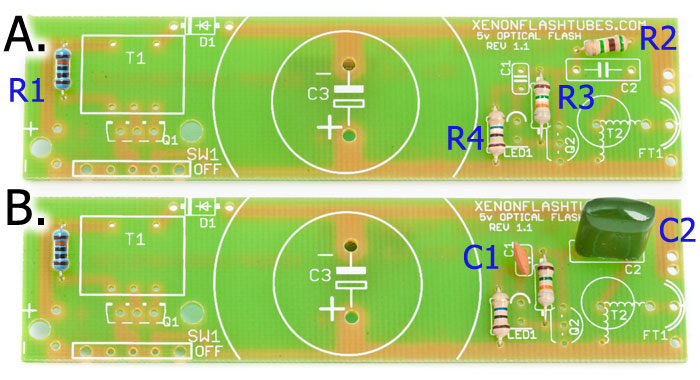
According to the part list, identify R1-R4 using the given color codes or refer to the image below.
Place R1,R2,R3 and R4 on the PCB, polarity doesn't matter.
Go ahead and place C1 and C2. quite simple: C1 is the orange disc shape component, and C2 is the rounded-corners-square green component marked "473".
Now solder them all in place and clip the excessive legs off the solder side.
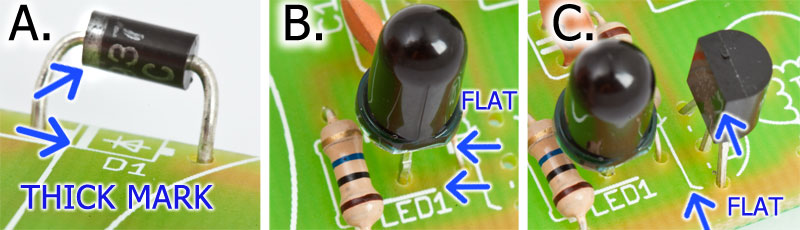
Now pay attention: insert the D1 diode into it's place, while the diode's marked white side is oriented to the PCB's marked bold white stripe.
Same for LED1, place it into the PCB, with its flat side to the PCB's marked flat side, like explained in the picture below.
Now for Q2 - it is the small black transistor half-round shape - place it into the PCB while its flat side is facing the flat side of the marking.
Take the T1 square yellow transformer which has 5 pins (XFT-1610) and place it, should snap in easily, and solder it.
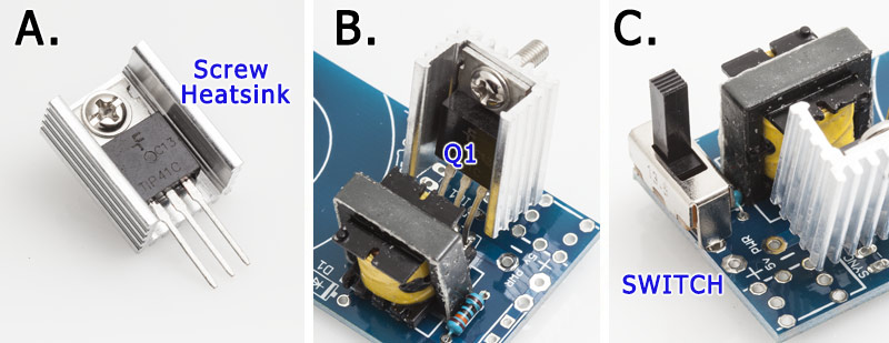
Q1 is the rectangle flat transistor (TO220 package). Screw Q1 to the heatsink as shown on the photo.
Place the assembly into the PCB with the black plastic side of Q1 facing the big transformer. Solder it keeping the full pinlegs length. As high as possible above the PCB, to keep enough space for the Sync jack.
And lastly, the little switch SW1, which comes right near the transformer:
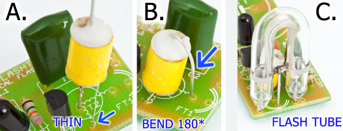
A little effort, just a few components left: the Trigger coil (yellow, 3 wires) , the U-shape flash tube, and the big capacitor.
The trigger coil T2 should be soldered with the 2-wires side facing down the PCB. the center thick wire going into the hole in the center of the round PCB marking, and the very thin wire at the same side of the coil is going to the small hole right below the circle.
The remaining third leg facing upwards, should be bent down 180 degrees and should be soldered in the nearest hole on the right.
Now solder the FT1 flash tube, while each of the wires snaps easily into their place near the Trigger coil:
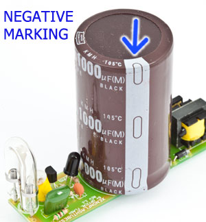
Place the BIG capacitor C3 into the PCB while the NEGATIVE PIN IS MARKED BY A WHITE STRIPE ALONG IT.
Polarity is extremely important here. so the marked side of the capacitor faces the "-" side of the PCB marking.
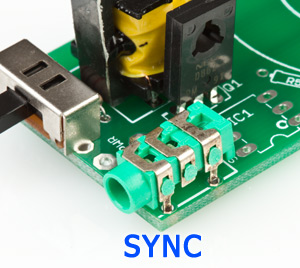
Place the 3.5mm Sync socket on the corner of the PCB, and solder it. The sync voltage through this socket is about 7v.
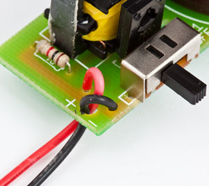
If you ordered a battery holder, or want to use a wall adapter, you can solder them directly to the PCB, according to the "PWR" + and - markings.
Don't forget it will accept a voltage of around 5v - 6v .
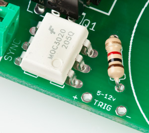
you can trigger the unit using an external 5v pulse source, like a micro-processor - INSTEAD of triggering with the optical flash detector. This is done by using a MOC3020 optocoupler (order here)
The optocoupler gives you an optically-isolated interface from the flash circuit power source, and the high voltage part, for a maximum safety.
just solder it in the IC1 place, and solder a 1K resistor (not supplied) at the R5 marking.
As you apply a voltage at the "TRIG" terminals (polarity matters), the unit will trigger the flash. .
A DIY assembly kit for Optically-triggered ("slave") Photography Flash unit, powered by 5v-6v (4xAA batteries)