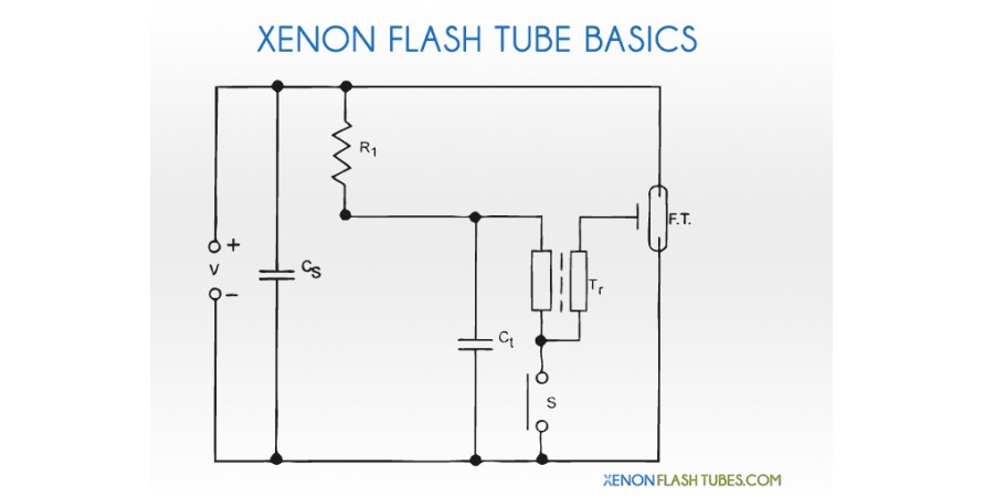
Contact: info@xenonflashtubes.com

Xenon Flash Tubes store

  • About
  • Corporate & Retailers
  • Custom modules
  • HOME
  • FLASH TUBES
    • LINEAR FLASHTUBES
    • General Linear lamps (Photo)
    • For Canon\Nikon Flashgun
    • BIG Linear lamps
    • Strobe lamps (stroboscopes)
    • ROUND FLASHTUBES
    • ROUND flash tubes (Studio)
    • Large RING-FLASH Lamp
    • OTHER SHAPES
    • U-shape (horse-shoe)
    • Helical (Spiral) shape
  • COMPONENTS
    • Other components
    • Trigger Coil Transformer
    • Capacitors
    • Other components
  • KITS & MODULES
    • Flash KITS & MODULES
    • PHOTO flash kits
    • Strobe module
    • Stage strobe light driver boards
    • Stage & Party strobes
    • 50w basic strobe
    • 300w basic strobe
    • 750w SMART Strobe
    • 1500w SMART Strobe
  • PICTURES
  • SCHEMATICS

Photography Optical slave Flash Kit

«   Back to Strobe Kits & Modules

5v Optical Flash Kit (DIY kit)           (instructions: click here)

Model: OPTICAL-SLAVE-KIT : DIY Assembly kit !
NEW VERSION: REV 1.2 (JAN-2013)
Soldering skills needed, comes as a DIY kit, with clear and easy instructions here
NEW: also available assembled. just add the assembly service below to the cart.

This kit is an Optical-triggered Powerful photography flash.
it powers using a 5v source like a wall adapter or 4xAA batteries,
And will automatically fire itself (by optical detection) when another flash is fired nearby.
NEW: Sync socket a 3.5mm sync socket is included to allow triggering by a sync cord.
OPTIONAL: You can also trigger the unit with an optocoupler (not included) to allow triggering with micro-processors (read here)

POWERFUL: The 50ws kit fires a flash as powerful as a FULL POWER FLASHGUN.

GREAT for DIY projects:
You can use this board as a basic learning kit on how Xenon flash works, or even use it as a base circuit and modify it according to your project needs.
It can easily help you in lighting different places in a scene or just as background lights... use your imagination !

WARNING:
This kit involves High Voltage up to 300v which is stored in big capacitors even long after turning the unit off. THIS VOLTAGE CAN KILL YOU. Never touch any of the components and always discharge the capacitor before working on it. Always keep in a well insulated project enclosure.

Specs
• Working voltage: 5v  (4v-6v)
• SYNC TRIGGER voltage: ~ 7v (compatible with Digital SLR)
•Assembly time: 5-15 minutes
• PCB Size: 29x90mm


► 50ws version
REV_1.2 In Stock !
  25.90 $
► 10ws version
REV_1.2 In Stock !
  21.90 $

Accessories:
Assembly service
for one kit. Add to the above products
  4.90 $
4xAA battery holder
Battery holder 4xAA
  1.90 $


Instructions
5v Optical Flash Kit (DIY kit) - Soldering instructions

Model: OPTICAL-SLAVE
DIY Assembly kit !

WARNING: This kit involves High Voltage up to 300v which is stored in big capacitors even long after turning the unit off. THIS VOLTAGE CAN KILL YOU INSTANTLY. Never touch any of the components and always discharge the capacitor before working on it. Always keep in a well insulated project enclosure.
BY FOLLOWING THESE INSTRUCTIONS YOU AGREE TO BE THE ONLY RESPONSIBLE FOR ANY DAMAGE THAT MIGHT BE CAUSED BY DOING SO.                         WORK CAREFULLY AND FOLLOW WARNINGS


Parts List

  • R1: 1K (Brown Black Red Gold); R2: 5.1M (Green Brown Green Gold); R3: 15K (Brown Green Orange Gold); R4: 10M (Brown Black Blue Gold)
  • C1: 0.01uF (marked 103);     C2: 0.047uF 630v (marked 473);     C3: 450v 220uF\1000uF (depending on your version)
  • D1: 1N4937 Fast 1A 600v;     LED1: TOPS-050 Photo Transistor (black color LED)
  • Q1: 2SD882;     Q2: MCR100L
  • T1: T-1610-6v square transformer;     T2: TC-36 round trgger coil
  • Misc-    SW1: 2-POS switch;     FT1: Xenon flash tube (U-shape);     3.5mm Sync socket


NEW! OPTIONAL:
You can trigger the flash using an optically isolated external signal. (read before you start)


Step 1: Place small components

According to the part list, identify R1-R4 using the given color codes or refer to the image below.
Place R1,R2,R3 and R4 on the PCB, polarity doesn't matter.
Go ahead and place C1 and C2. quite simple: C1 is the orange disc shape component, and C2 is the rounded-corners-square green component marked "473".
Now solder them all in place and clip the excessive legs off the solder side.


Step 2: Continued

Now pay attention: insert the D1 diode into it's place, while the diode's marked white side is oriented to the PCB's marked bold white stripe.
Same for LED1, place it into the PCB, with its flat side to the PCB's marked flat side, like explained in the picture below.
Now for Q2 - it is the small black transistor half-round shape - place it into the PCB while its flat side is facing the flat side of the marking.


Step 3: Transformer

Take the T1 square yellow transformer which has 5 pins (T-1610) and place it, should snap in easily, and solder it.
Q1 is the rectangle flat transistor. find its metallic side, and place it into the PCB with the metallic side facing the big transformer. The transistor's marking should be visible to you.
And lastly, the little switch SW1, which comes right near the transformer:


Step 4: Trigger coil and Flash Tube

A little effort, just a few components left: the Trigger coil (yellow, 3 wires) , the U-shape flash tube, and the big capacitor.
The trigger coil T2 should be soldered with the 2-wires side facing down the PCB. the center thick wire going into the hole in the center of the round PCB marking, and the very thin wire at the same side of the coil is going to the small hole right below the circle.
The remaining third leg facing upwards, should be bent down 180 degrees and should be soldered in the nearest hole on the right.
Now solder the FT1 flash tube, while each of the wires snaps easily into their place near the Trigger coil:


Step 5: BIG power !

Place the BIG capacitor C3 into the PCB while the NEGATIVE PIN IS MARKED BY A WHITE STRIPE ALONG IT.
Polarity is extremely important here. so the marked side of the capacitor faces the "-" side of the PCB marking.


Step 6: Solder Sync port and power source

Place the 3.5mm Sync socket on the corner of the PCB, and solder it. The sync voltage through this socket is about 7v.

If you ordered a battery holder, or want to use a wall adapter, you can solder them directly to the PCB, according to the "PWR" + and - markings.
Don't forget it will accept a voltage of around 5v - 6v .


OPTIONAL: opto-Isolated triggering

you can trigger the unit using an external 5v pulse source, like a micro-processor - INSTEAD of triggering with the optical flash detector. This is done by using a MOC3020 optocoupler (order here)
The optocoupler gives you an optically-isolated interface from the flash circuit power source, and the high voltage part, for a maximum safety.

just solder it in the IC1 place, and solder a 1K resistor (not supplied) at the R5 marking.
As you apply a voltage at the "TRIG" terminals (polarity matters), the unit will trigger the flash. .


SAFETY GUIDELINES:
- Use a project enclosure for the finished circuit
- Never touch any of the components or any other conductive surface EVEN AFTER DISCONNECTED form power !
- Always monitor the big capacitor voltage using a voltmeter if you are unsure !
- Always empty the capacitor before working on the circuit. either trigger a flash after disconnecting power, or by CAREFULLY connecting a 100K resistor between capacitor's terminals (dont touch it !), and monitor with voltmeter.

Done ! now you can power it.


ORDER NOW !


Troubleshooting :

There are very few things that can go wrong here. please check that:

  • Have you soldered D1 diode with the white marking towards the thick marking on the PCB ?
  • Have you soldered LED1 with the flat side in the direction of the flat line on the PCB ?
  • Have you soldered Q1 with the metallic part facing the yellow transformer ?
  • Have you soldered Q2 with the flat side facing the flat mark on the PCB ?
  • Have you soldered C3 big capacitor with the negative marking (long white strip) to the "-" marking on the PCB ?
  • Have you switched ON the SW1 switch ?
  • Are you sure your batteries are fully charged or your power source is working ?


Back to top ^


  • Use the kits at your own risk.
  • Kits are shipped without power source or power cable.


Shipping

We ship worldwide !

    Flat-rate worldwide shipping starts at only $8. Click the "view cart" button to calculate shipping.

Express

    Express shipping is available by DHL or EMS. please contact us with your order details and shipping destination.

Corporate

Large quantity orders

    please contact us with your order details so we can reply with our best offer for volume discounts.

On-demand customized products

    Our Development department is at your disposition if you need special flash tubes or complete modules with power-driver. click for more information

Category items

  • .
    • Mac book
    • Mac book Air
    • iMac
    • Mac mini
    • Laptops
    • Mouse
    • Keyboard
    • Hard

Shipping:

WORLDWIDE SHIPPING via airmail. Orders usually arrive within 10-21 days worldwide.

EMS / DHL EXPRESS (Optional) - please contact us if you need express shipping by EMS or DHL Express.

Payment methods:

Contact
Email: info@xenonflashtubes.com

About us

We are serving hundreds of customers around the world, including: Manufacturers and factories, Research institutes, Universities, development centers, Retailers and more.

Customized Modules

Our Development department is at your disposition if you need us to design and manufacture flash lamps' driver and power supplies circuits and PCBs.
click here for more information
  • HOME
  • About
  • Corporate & Retailers
  • Custom modules
  • Contact Us

Copyright © 2012 XENONFLASHTUBES.com All rights reserved.

top